An overview of an ongoing experimental investigation into using embroidery techniques to produce functional logic elements.
The goal is to create textile electromagnetic switches that reliably closes separated circuits. An embroidered version of a SPDT relay – ‘Single Pole Double Throw’. A common terminal connects to either of two others.
Input and output states ‘LOW’ and ‘HIGH’ states are controlled by the north respectively south pole facing up.
Experiments into crochet relays can be found here.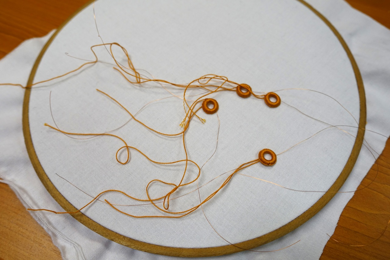
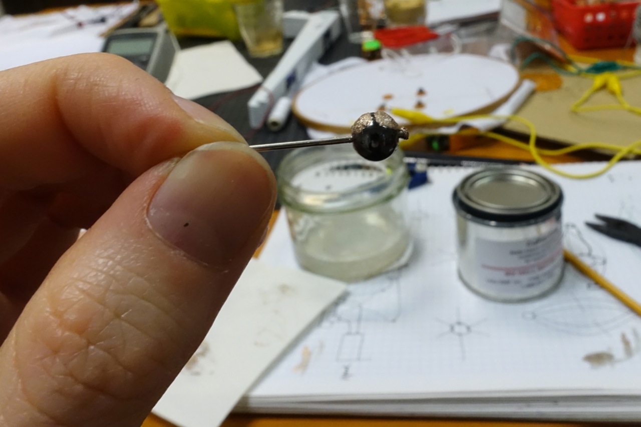
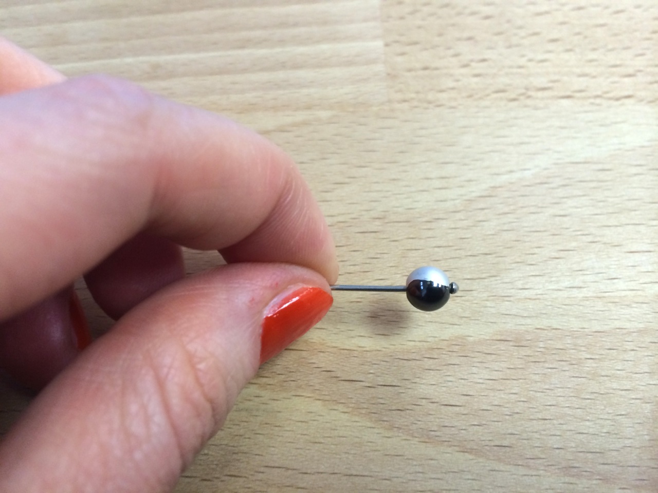
Painting segments of a magnetic bead to close individual circuits. Trying to make a circuit for an NOT gate, with the output logic being opposite to the input logic, eg. opposite sides facing up. The copper paint doe not close the contact very reliably though. Additional pressure needs to be applied in order to actually close the circuit with low enough resistance to activate the following coil.
Testing with a neodym magnets instead of magnetic beads. The form of the neodym magnets is not ideal for this kind of embroidery technique, so special ways to mount and close the contact have to be found. As neodym magnets are conductive, areas that are not supposed to touch need to be insulated.
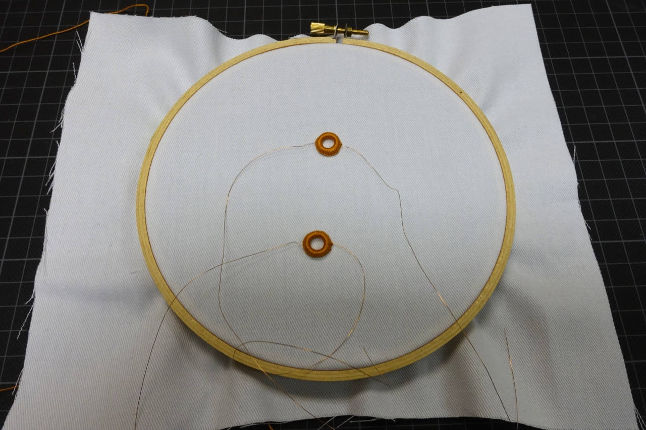
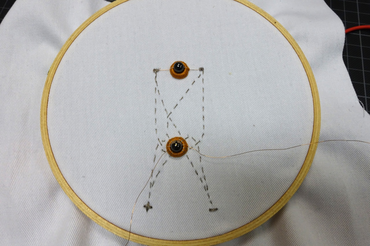
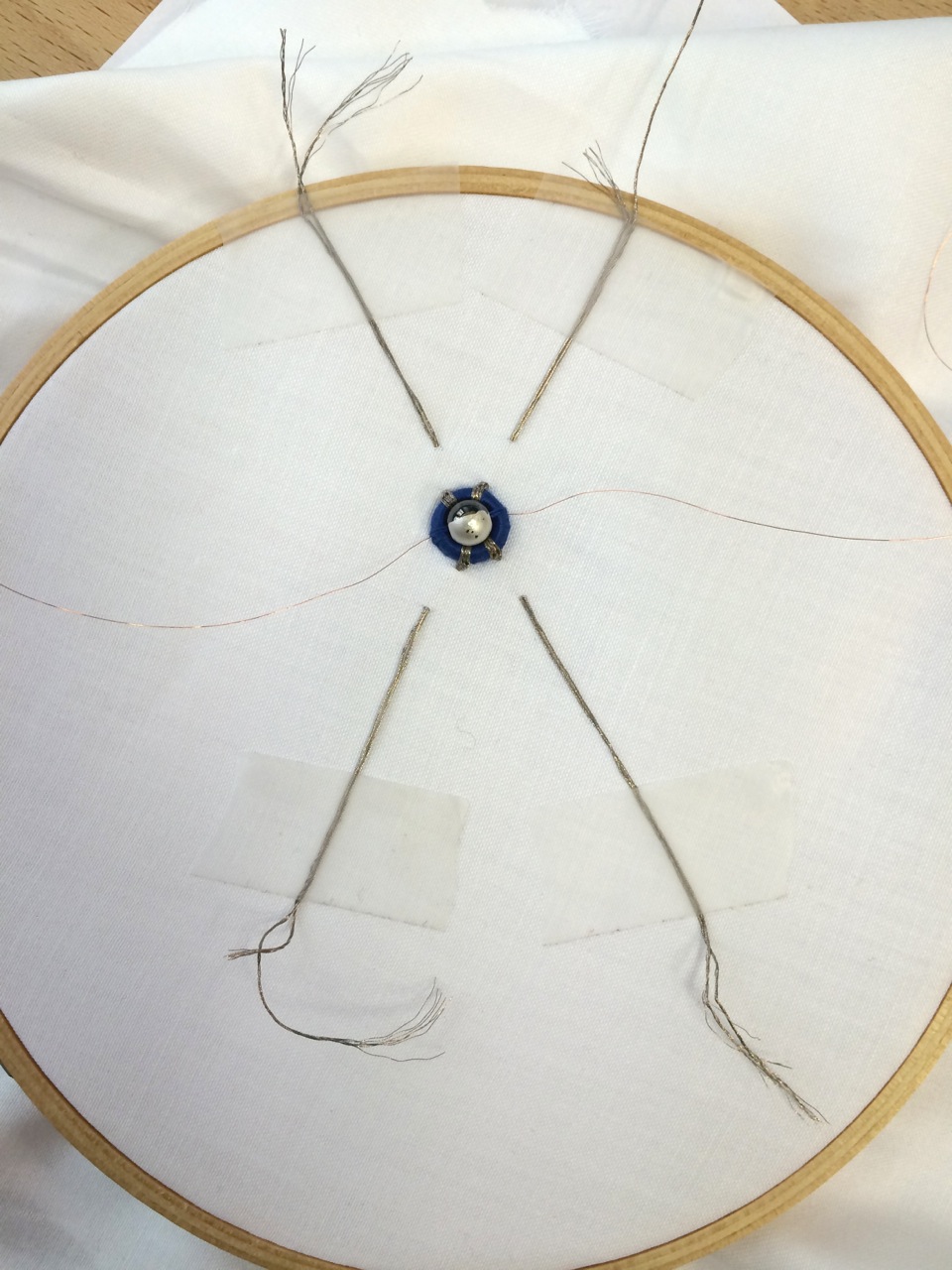
Contact points are at the bottom inner side of the coil.
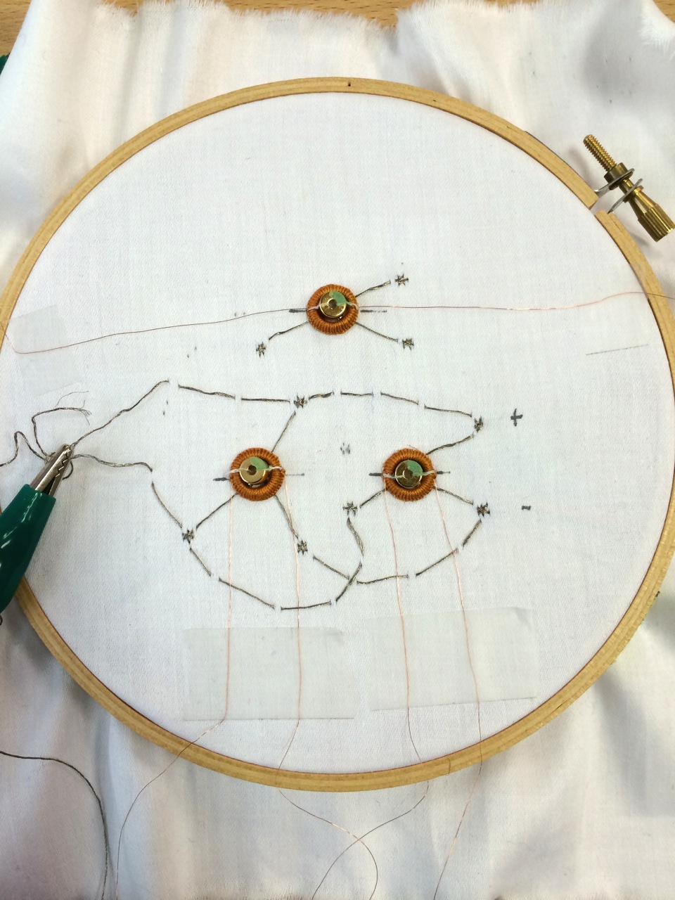
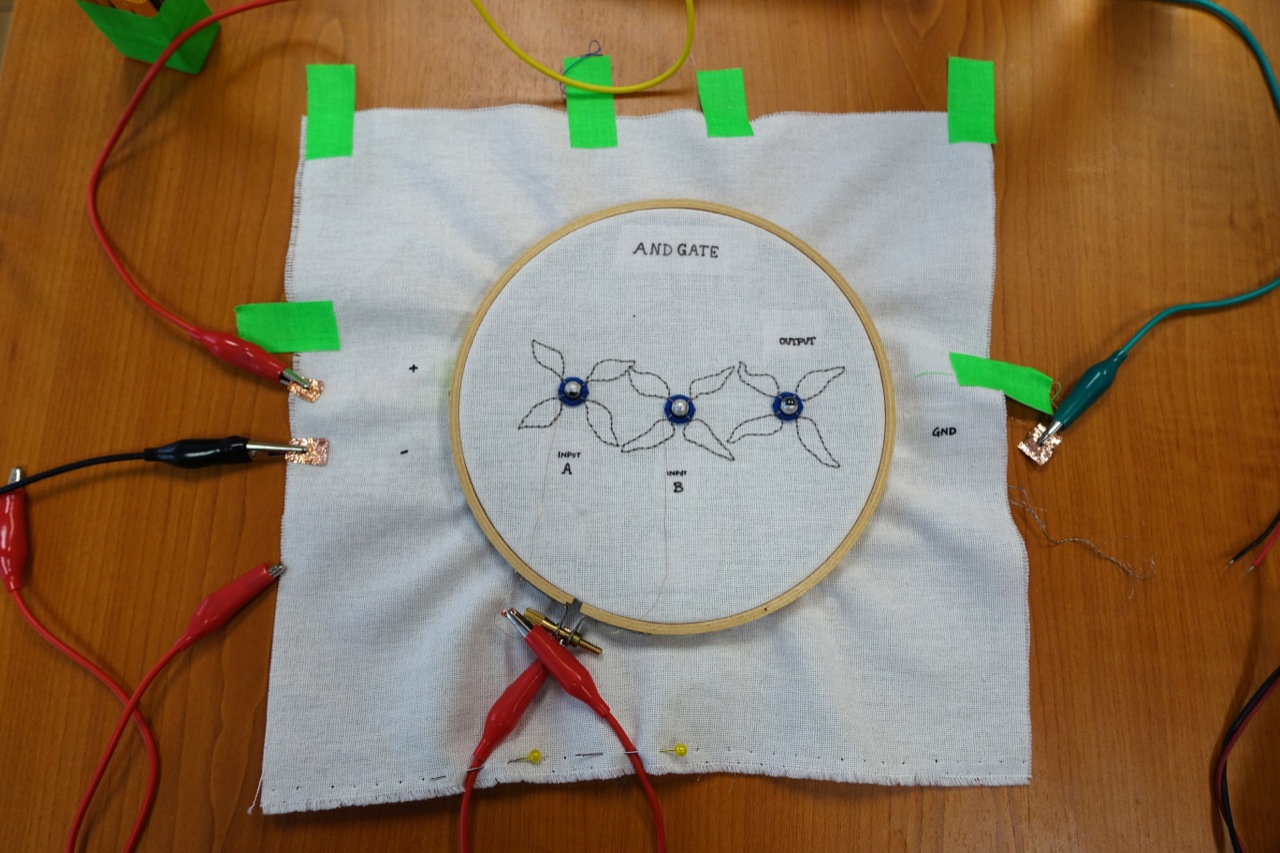
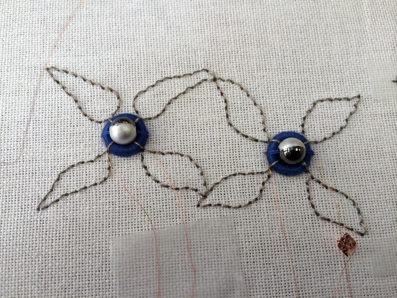
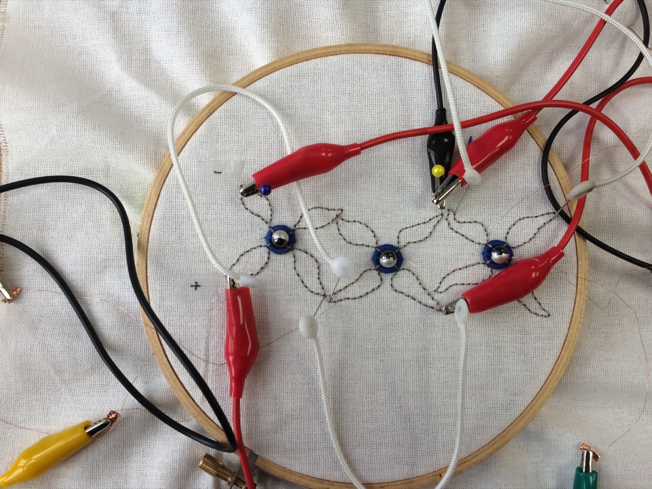
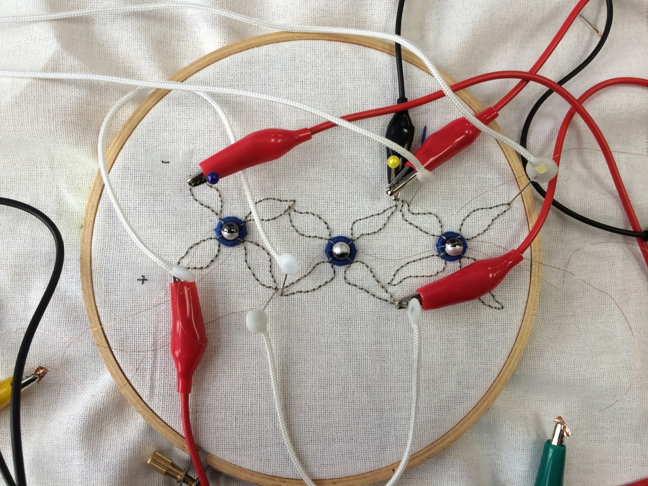
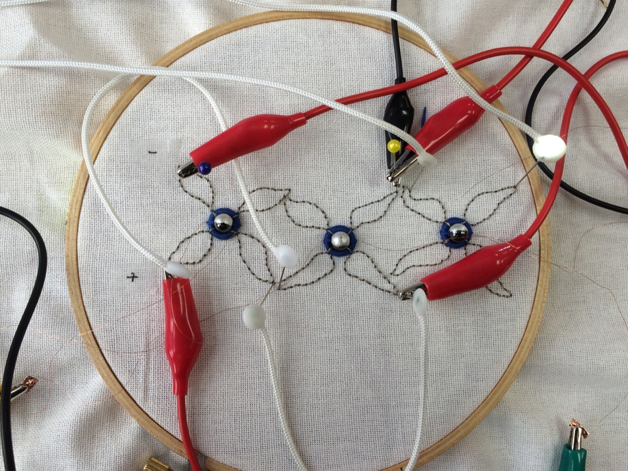
To reduce the number of beads needed, and thus the risk of failure, several coils could also be embroidered within one ornament. Two coils for the input and one for control form a total of three individually controllable coils within one ornament. The bead on top shows the output.
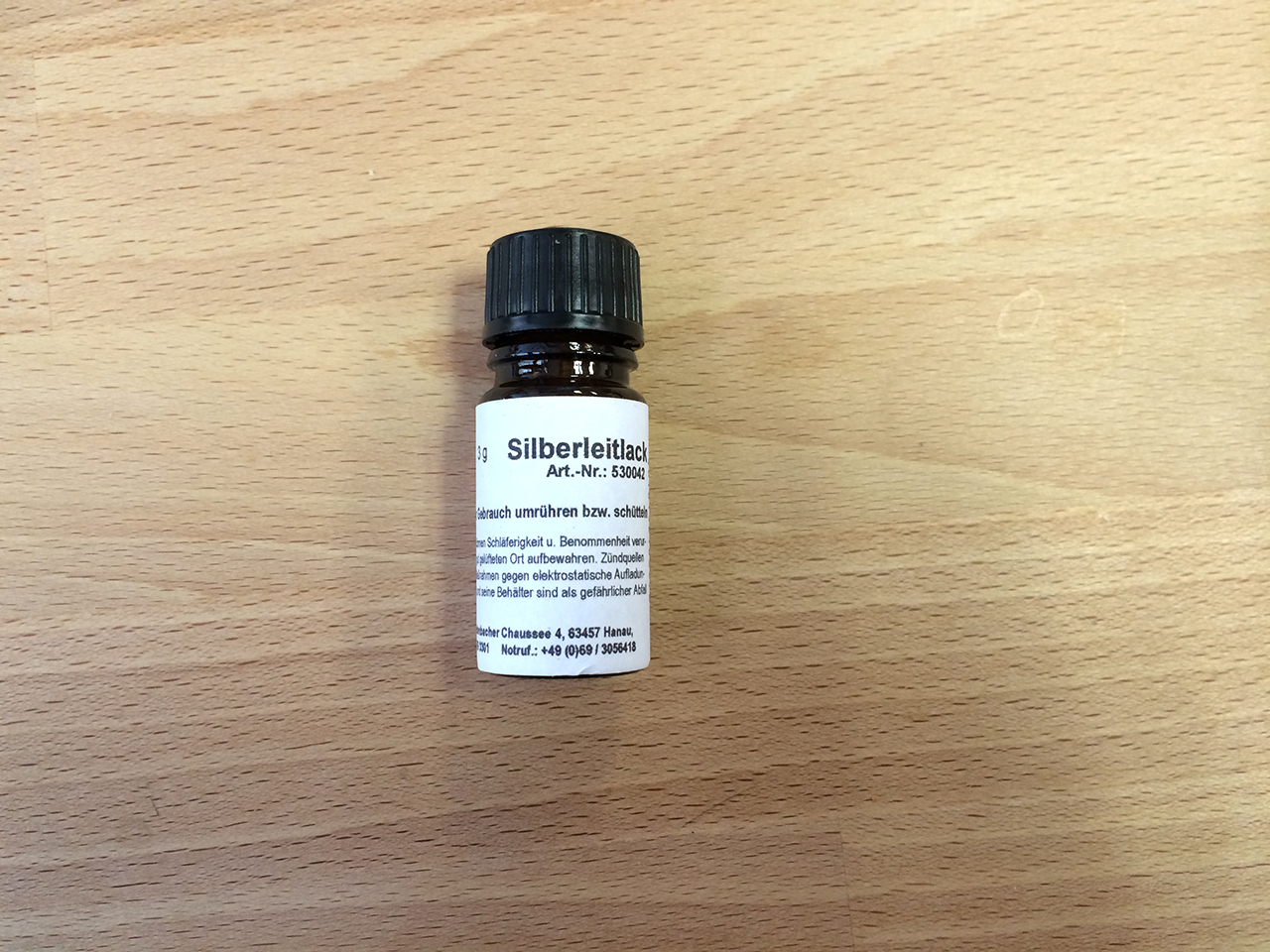
Painting the beads with silver paint (instead of copper paint) to improve closing the contact.
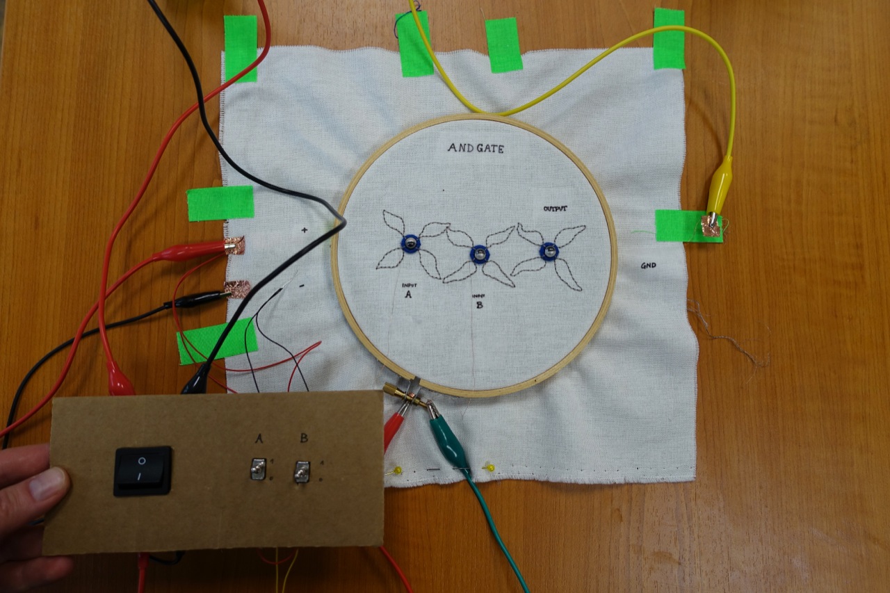
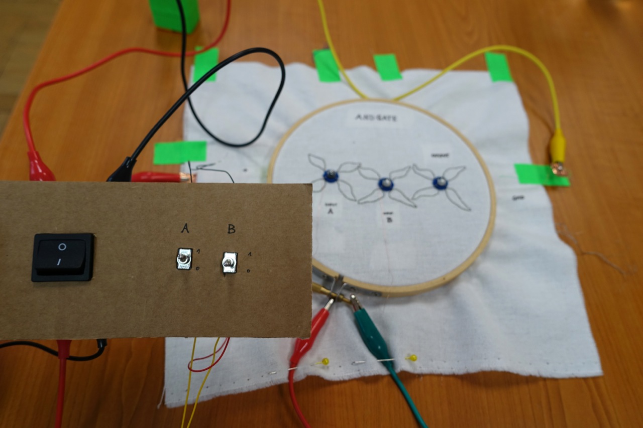
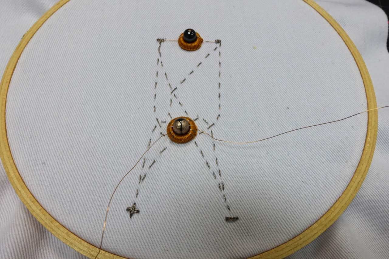
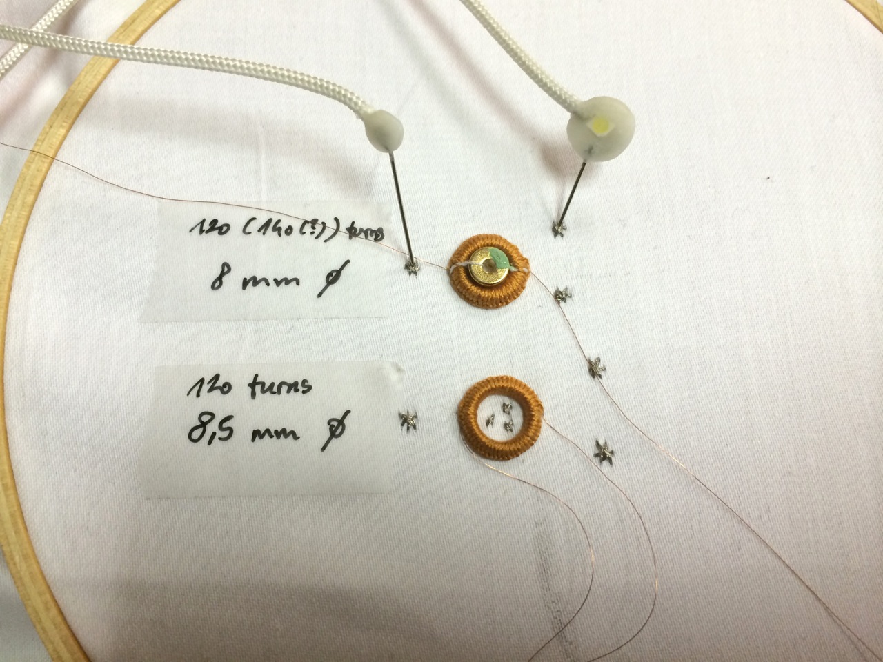
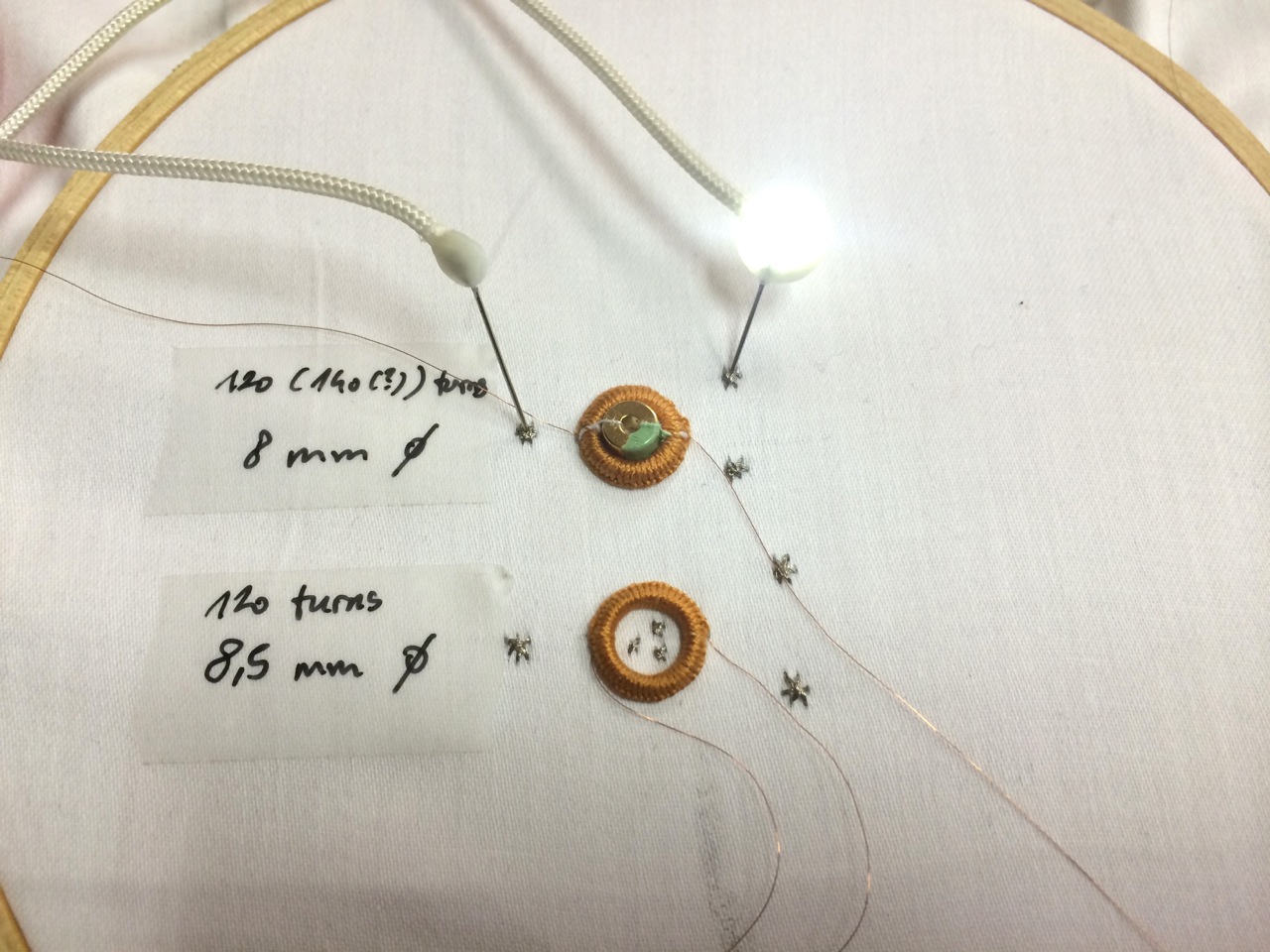
Including LEDs in the embroidery to indicate the output state of an AND grate. Realised with 3 coils that are combined in one ornament.
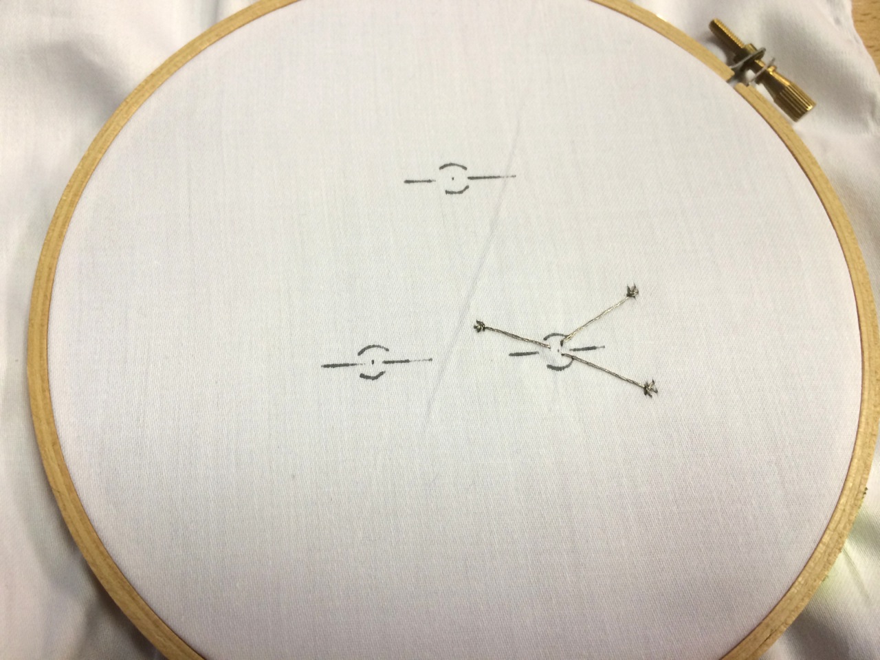
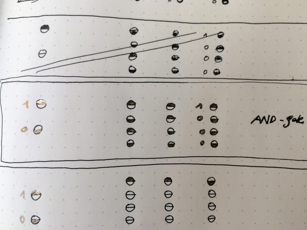
Embroidered AND gate with a very simple function pattern.
Truth table indicating the beads’ states for ‘LOW=0’ and ‘HIGH=1’ and different input/outputs in the embroidered logic.
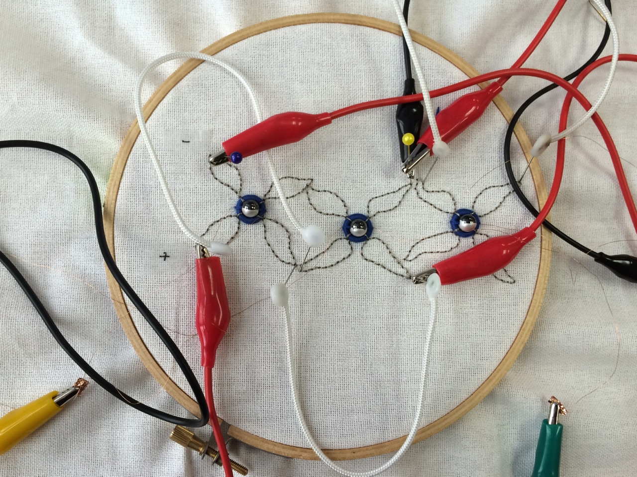
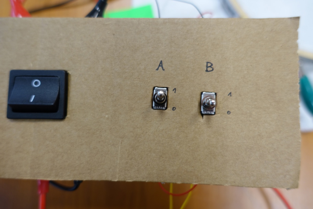
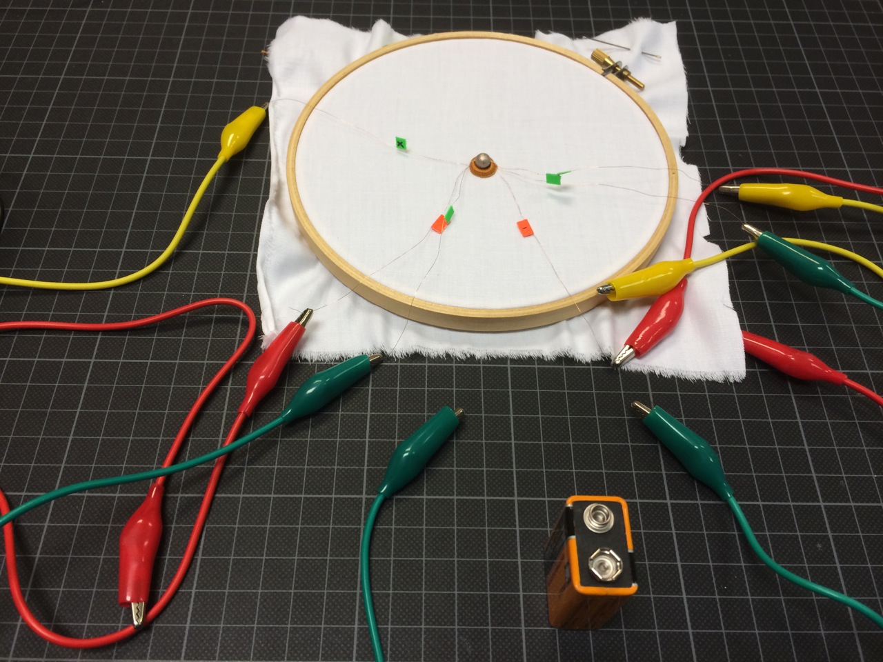
For controlled testing input, power supply and input are connected to switches.