The goal of measuring (self-made) textile capacitors is to evaluate their functionality compared to commercial hardware capacitors.
A capacitor is defined as a passive two-terminal electronic component used to store an electric charge in an electric field. It consists of one or more pairs of electrical conductors separated by a dielectric (i.e. insulator).
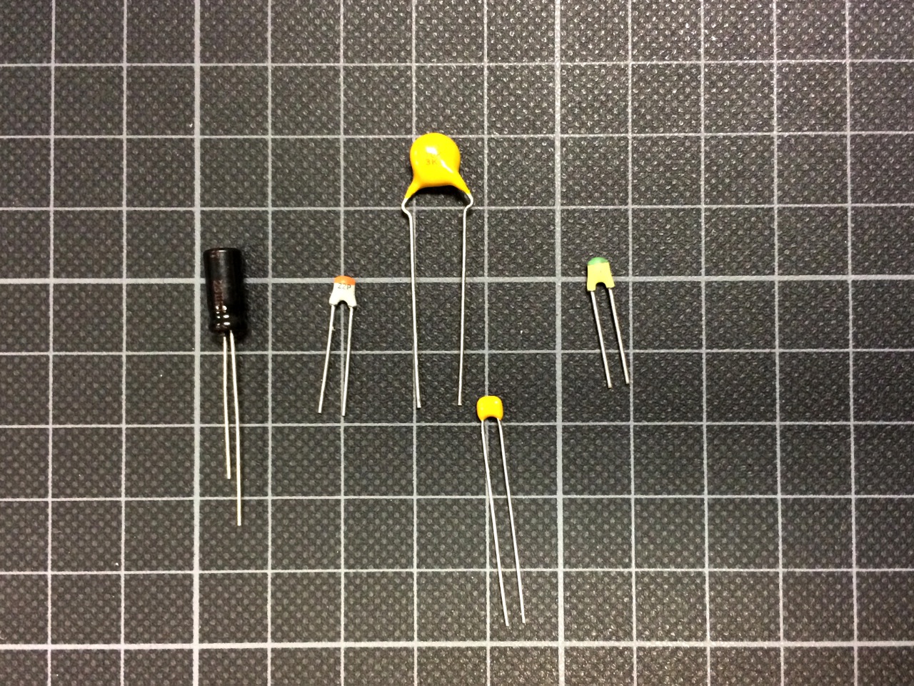
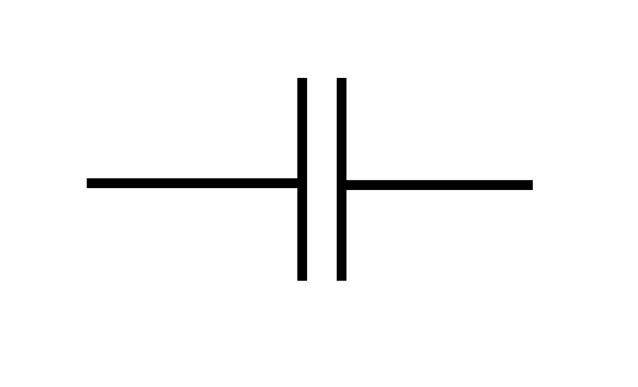
Hardware Capacitor and Electronic Symbol
Measurement Setup and Goals
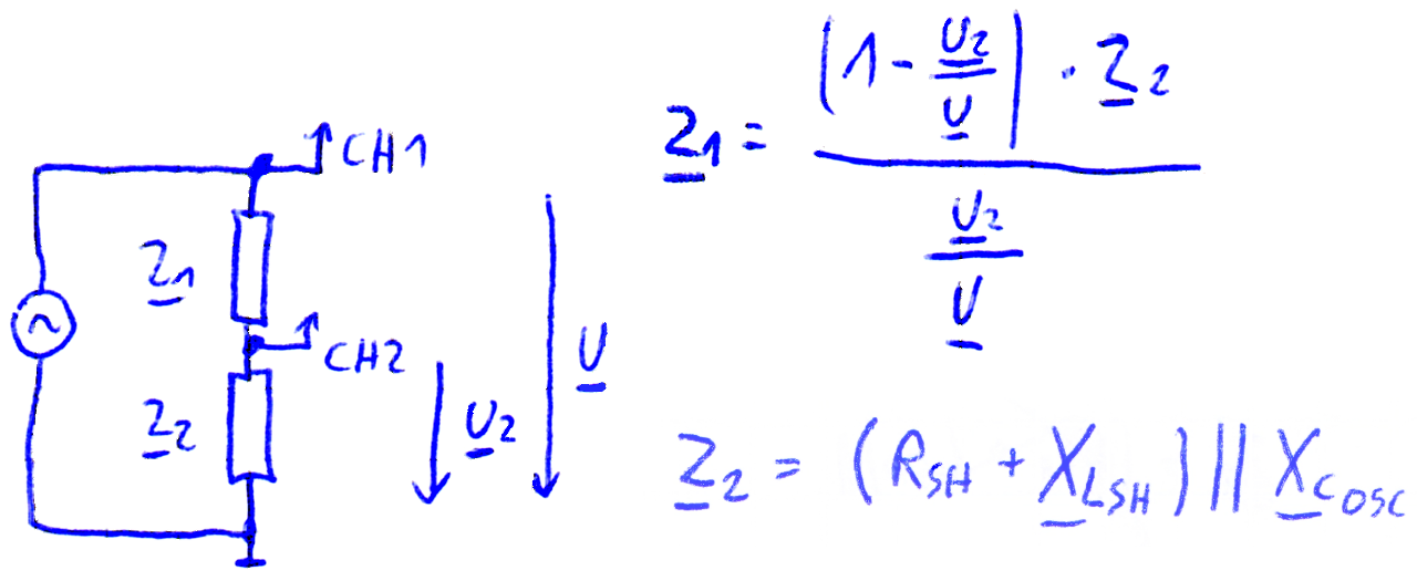
To measure a capacitor’s functionality and quality we want to measure how it behaves in different frequencies. An ideal capacitor should always have a phase difference of 90° between voltage and current. In reality, a capacitor has also unwanted resistance that is responsible for unwanted energy losses, quantified by the dissipation angle or the Q-factor. It has also an inductance that counteracts the capacitance, at too high frequencies the inductance takes over and the capacitor starts behaving like an inductor. This defines the maximum frequency the capacitor can be used in a regular way.
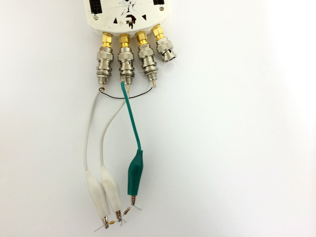
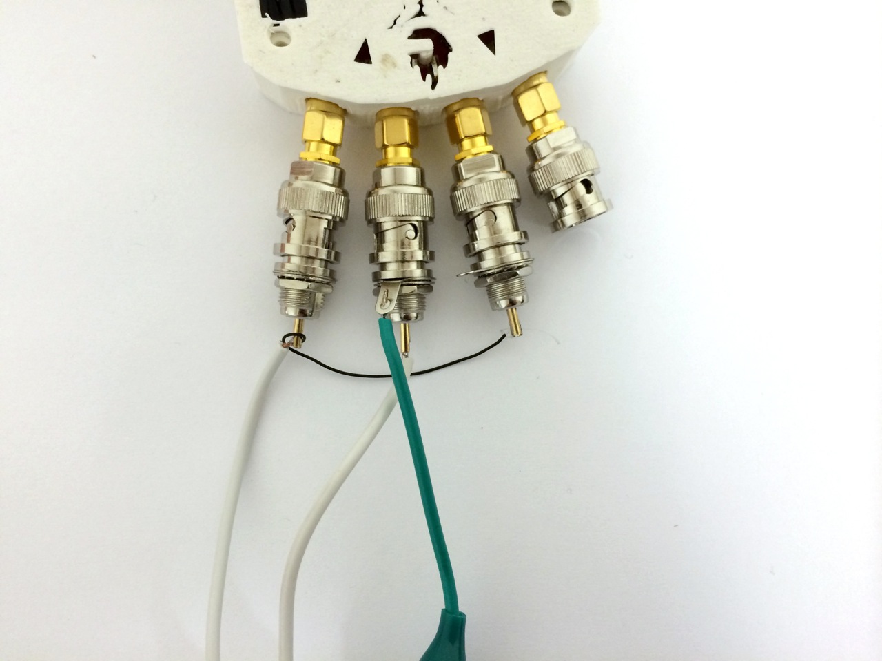
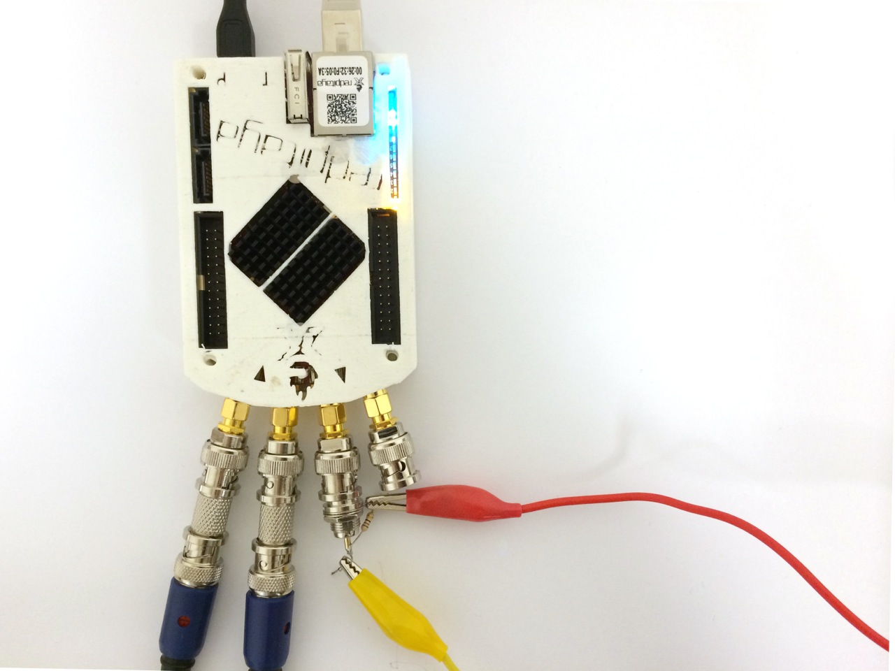
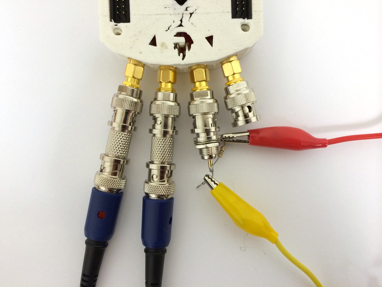
For measuring we rely on the RedPitaya oscilloscope and signal generator using a setup and software described here Gain/Phase/Impedance Analyser. We changed some code to output the data more compact and without SI units. The shunt resistor value needs to be changed according to the measured capacity range.
The problem we encountered is that this setup cannot produce very accurate data at high frequencies. One step to get to more reliable measurements is to use the GPlanalyser tool to output only gain/phase data directly into a spreadsheet calculation so we can erase some of the errors though compensation measurements. Still, the setup is very sensible to any instability in the system such as length and position of measurement cables when testing high frequencies. As this is a problem general to testing equipment in this price range, we had to determine a range where the results can be trusted and shift our goal with this setup to measure and test capacitors in the frequency range below 1 MHz and being able to compare the behaviours of different capacitors at higher frequencies.
Schematic of the Measurement Setup
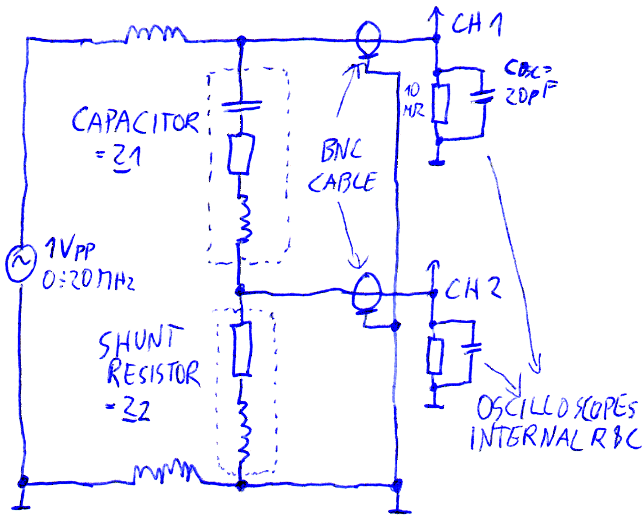
Simplified Schematic for Calculations
(all relevant parts included into Z2, influence of BNC cables ignored)
First test setup
Improved test setup
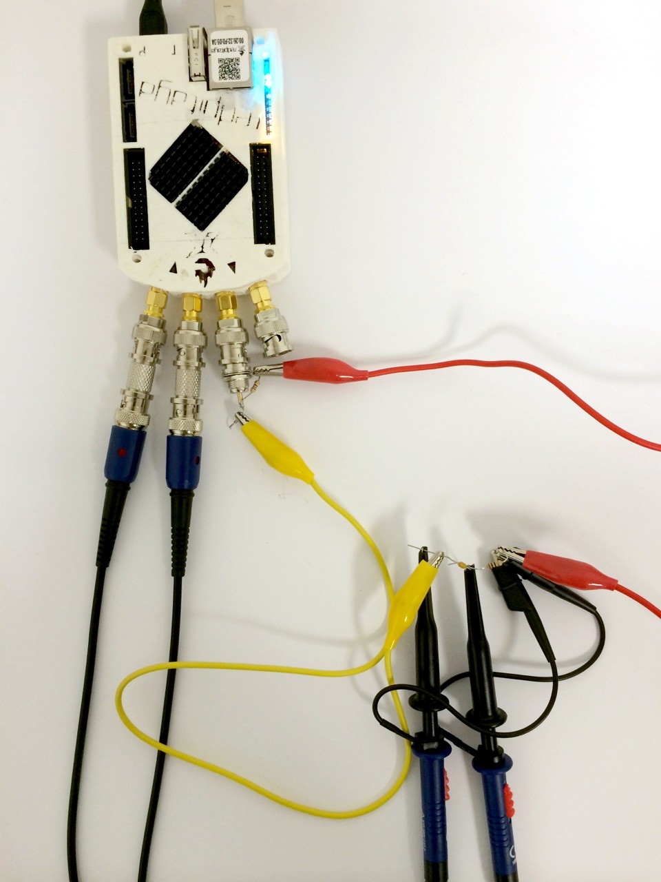
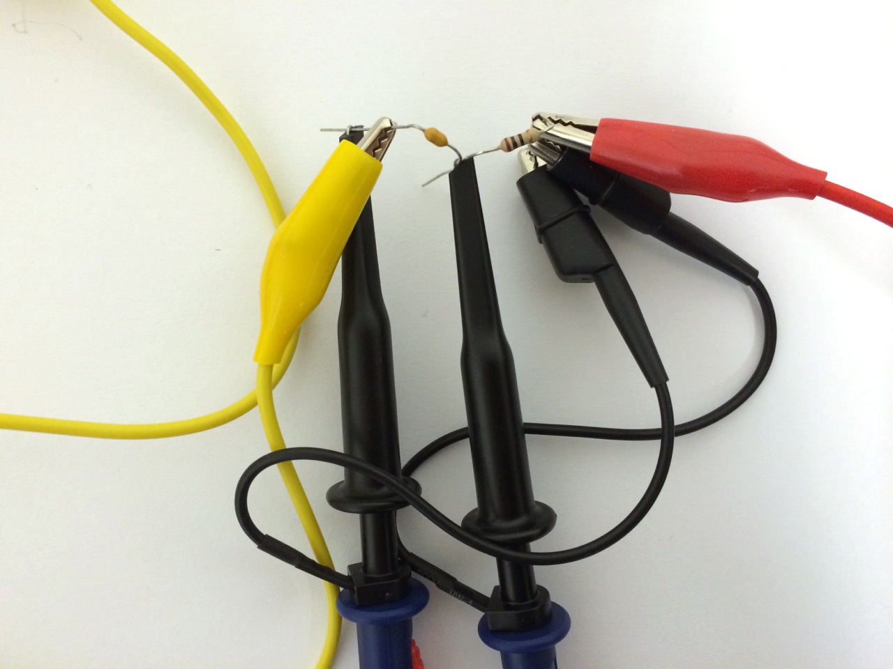
To minimize any stray capacitances and inductances that would change with cable positions, we used a setup with two probe heads, as the capacitance and inductance of coax probe cables is bigger, but more stable. The resulting delay is not harming the measurement, as both signals do travel the same length.
Measurement Results
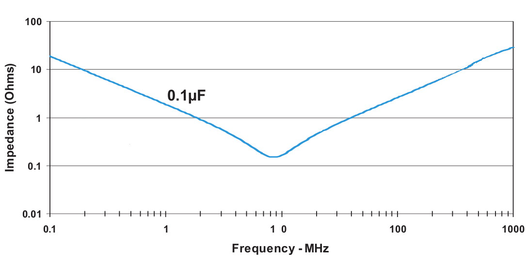
100nF store bought capacitor, image from datasheet
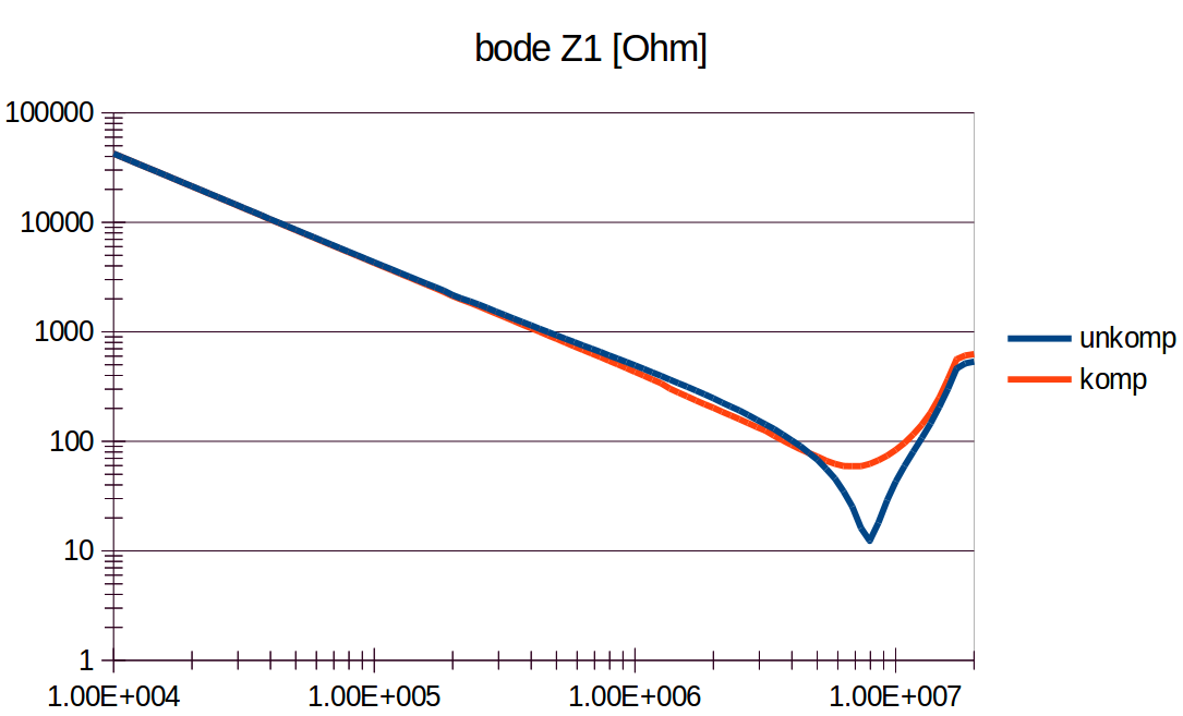
100nF store bought capacitor, measured with our setup
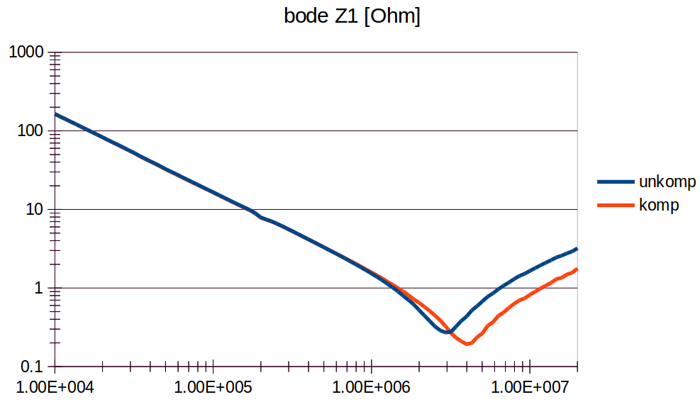
The red line shows the compensated measurement. The lowest point is where the unwanted inductance takes over. Left of that, we see the behaviour of a capacitor (impedance is proportional to 1/f), to the right the behaviour of a inductance (impedance is proportional to f)
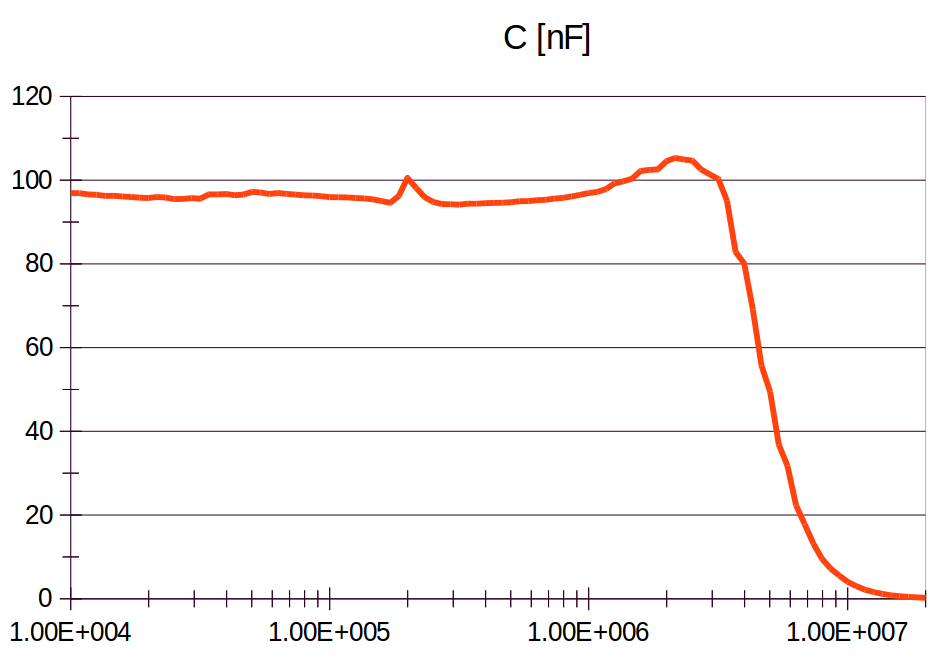
100nF store bought capacitor, measuring capacity
Comparison between knitted capacitor and hardware capacitor
Hardware capacitor
Knitted capacitor